Tuesday, 7 March 2017
Wednesday, 1 March 2017
Digital Clock with 8 digits 7 Segment Module (without RTC)

Disini kita akan belajar membuat sebuah Jam Digital sederhana,karena hanya membutuhkan 1 unit 8 digit Seven Segmen (dengan 1 IC Max7219) dan Sebuat controller Arduino (Uno/Nano/Pro mini).
Disini kita dapat menambah kan Opsi 3 buat push button sebagai tombol setting manual Jam nya.
Berikut bahan-bahan yang kita butuhkan :
1unit Arduino Uno atau Arduino Nano atau Arduino Pro mini
1unit display Seven Segment 8digit Max7219
3buah tombol Push button
beberapa helai kabel jumper duppon

Schematic 8 Digits 7 Segment Display dengan Single Controller Max7219

Schematic 3 Push Button Active Low

Library Arduino yang kita butuhkan :
Library Segment Led Controller download disini atau download disini.
Library Push Button download disini.
Extract dan masukan Library yang dibutuhkan diatas (salah satu saja) ke dalam folder Libraries Arduino (master foldernya saja)
Windows 64bit : C:\ Program Files (x86) \ Arduino \ libraries
Windows 32bit : C:\ Program Files \ Arduino \ libraries
Windows 64bit : C:\ Program Files (x86) \ Arduino \ libraries
Windows 32bit : C:\ Program Files \ Arduino \ libraries
Wiring Arduino dengan Display Segment :
wiring Module Display 8digit 7segment ke Arduino (Uno)// Arduino Pin D12 to DIN 8digit 7segment
// Arduino Pin D11 to CLK 8digit 7segment// Arduino Pin D10 to CS 8digit 7segment
// Arduino Pin 5V to VCC 8digit 7segment
// Arduino Pin GND to GND 8digit 7segment
Wiring Arduino dengan Display Segment :
// Arduino Pin D4 to Push Button SETUP
// Arduino Pin D3 to Push Button (+) increase digit
// Arduino Pin D2 to Push Button (-) decrease digit
// Arduino Pin GND disambungkan dengan Common pin push button
(lihat schematic Push button diatas untuk lebih jelasnya)
kita tidak perlu memberikan Resistor Pull-Up seperti pada gambar karena kita akan memakai
internal R Pullup milik Digital Pin Arduino.
Dani's Simple Digital Clock Sourche Code
Copy paste sourche code dibawah ini ke dalam Arduino IDE kemudian upload ke Arduino Board Anda. Anda juga bisa download .ino file nya disini.
#include "LedControl.h" //Memanggil library Led Control
#include//Memanggil library Push Button
//wiring Module Display 8digit 7segment ke Arduino (Uno)
// Arduino Pin D12 to DIN,
// Arduino Pin D11 to CLK,
// Arduino Pin D10 to CS,
// No.of devices is 1 (Display Urutan ke 1)
//Setup Tombol Setting
#define DN_PIN 2 //Decrease Button
#define UP_PIN 3 //Increase Button
#define SET_PIN 4 //Setup Button
#define PULLUP true //Mengaktifkan internal Pull Up
#define INVERT true
#define DEBOUNCE_MS 20
#define REPEAT_FIRST 500
#define REPEAT_INCR 100
//Declare push buttons
Button btnUP(UP_PIN, PULLUP, INVERT, DEBOUNCE_MS);
Button btnDN(DN_PIN, PULLUP, INVERT, DEBOUNCE_MS);
Button btnSET(SET_PIN, PULLUP, INVERT, DEBOUNCE_MS);
//////////////////////////////////////////
// Example by Dani Rajacell //
// Mohon tetap mencantumkan sumber //
//apabila menggunakan example kode ini //
//////////////////////////////////////////
LedControl lc=LedControl(12,11,10,1); // DIN,CLK,CS,No.
enum {WAIT, INCR, DECR}; //The possible states for the state machine
uint8_t STATE; //The current state machine state
int count; //The number that is adjusted
int lastCount = -1; //Previous value of count (initialized to ensure it's different when the sketch starts)
unsigned long rpt = REPEAT_FIRST; //A variable time that is used to drive the repeats for long presses
//Variable penyimpan logika setup
uint8_t setMode = 8;
uint8_t setRun = 0;
//Pengambilan waktu dari compiller
uint32_t targetTime = 0;
uint8_t conv2d(const char* p) {
uint8_t v = 0;
if ('0' <= *p && *p <= '9')
v = *p - '0';
return 10 * v + *++p - '0';
}
//Mengambil waktu jam dari waktu Compiler Arduino IDE
uint8_t hh = conv2d(__TIME__), mm = conv2d(__TIME__ + 3), ss = conv2d(__TIME__ + 6);
uint8_t hh1 = hh%10, mm1 = mm%10, ss1 = ss%10; // mengambil digit kedua
uint8_t hh2 = (hh%100)/10, mm2 = (mm%100)/10, ss2 = (ss%100)/10; // mengambil digit pertama
void setup()
{
//Serial.begin (115200);
// Initialize the MAX7219 device
// Kondisi default Max7219 saat power ON adalah Standby jadi harus kita aktifkan dulu...
lc.shutdown(0,false); // Enable display
lc.setIntensity(0,12); // Set brightness level (Level Kecerahan : 0 sampai 15)
writeRJC();
lc.clearDisplay(0); // Clear display register (Mengkosongkan tampilan segment)
}
//////////////////////////////////////////
// Example by Dani Rajacell //
// Mohon tetap mencantumkan sumber //
//apabila menggunakan example kode ini //
//////////////////////////////////////////
void loop(){
if (targetTime < millis()) {
targetTime = millis() + 1000;
ss1++; // Advance second
if (ss1 == 10) {
ss1 = 0;
ss2++;
if (ss2 == 6) {
ss2 = 0;
mm1++; // Advance minute
if (mm1 == 10) {
mm1 = 0;
mm2++;
if (mm2 == 6) {
mm2 = 0;
hh1++; // Advance hour
if (hh1 == 10) {
hh1 = 0;
hh2++;}
if (hh2>=2 && hh1>=4) {
hh2=0;
hh1=0;
}
}
}
}
}
}
lc.setDigit(0,7,hh2,false);
lc.setDigit(0,6,hh1,false);
lc.setChar(0,5,'-',false);
lc.setDigit(0,4,mm2,false);
lc.setDigit(0,3,mm1,false);
lc.setChar(0,2,'-',false);
lc.setDigit(0,1,ss2,false);
lc.setDigit(0,0,ss1,false);
setupClock ();
}
//////////////////////////////////////////
// Example by Dani Rajacell //
// Mohon tetap mencantumkan sumber //
//apabila menggunakan example kode ini //
//////////////////////////////////////////
void setupClock (void) {
btnUP.read(); //read the buttons
btnDN.read();
btnSET.read();
if (hh2==2 && hh1>3){hh1=0;}
if (setMode==2){setMode=3;}
if (setMode==5){setMode=6;}
if (setMode == 9){writeSetup(); setMode = 0; setRun=1;}
if (setMode == 8 && setRun == 1){writeFinish(); setRun=0;}
lc.setLed(0,setMode,0,true);
switch (STATE) {
case WAIT: //wait for a button event
if (btnSET.wasPressed())
{ setMode = setMode+1; if (setMode == 10)setMode=0;}
if (btnUP.wasPressed())
STATE = INCR;
else if (btnDN.wasPressed())
STATE = DECR;
else if (btnUP.wasReleased()) //reset the long press interval
rpt = REPEAT_FIRST;
else if (btnDN.wasReleased())
rpt = REPEAT_FIRST;
else if (btnUP.pressedFor(rpt)) { //check for long press
rpt += REPEAT_INCR; //increment the long press interval
STATE = INCR;
}
else if (btnDN.pressedFor(rpt)) {
rpt += REPEAT_INCR;
STATE = DECR;
}
break;
case INCR: //increment the counter
if (setMode==1 && ss2<5)ss2=ss2+1;
if (setMode==0 && ss1<9)ss1=ss1+1;
if (setMode==4 && mm2<5)mm2=mm2+1;
if (setMode==3 && mm1<9)mm1=mm1+1;
if (setMode==7 && hh2<2)hh2=hh2+1;
if (setMode==6 && hh1<9 && hh2<2)hh1=hh1+1;
if (setMode==6 && hh1<3 && hh2==2)hh1=hh1+1;
STATE = WAIT;
break;
case DECR: //decrement the counter
if (setMode==1 && ss2>0)ss2=ss2-1;
if (setMode==0 && ss1>0)ss1=ss1-1;
if (setMode==4 && mm2>0)mm2=mm2-1;
if (setMode==3 && mm1>0)mm1=mm1-1;
if (setMode==7 && hh2>0)hh2=hh2-1;
if (setMode==6 && hh1>0)hh1=hh1-1;
STATE = WAIT;
break;
}
}
//////////////////////////////////////////
// Example by Dani Rajacell //
// Mohon tetap mencantumkan sumber //
//apabila menggunakan example kode ini //
//////////////////////////////////////////
void writeSetup() {
lc.setDigit(0,7,5,false);
lc.setChar(0,6,'e',false);
lc.setRow(0,5,B00001111);
lc.setRow(0,4,B00111110);
lc.setChar(0,3,'p',false);
lc.setChar(0,2,'-',false);
lc.setChar(0,1,'-',false);
lc.setChar(0,0,'-',false);
delay(1000);
if(ss1<9)ss1=ss1+1;
lc.clearDisplay(0);
}
void writeFinish() {
lc.setRow(0,7,B01000111);
lc.setRow(0,6,B00110000);
lc.setRow(0,5,B00010101);
lc.setRow(0,4,B00110000);
lc.setDigit(0,3,5,false);
lc.setRow(0,2,B00010111);
lc.setChar(0,1,'-',false);
lc.setChar(0,0,'-',false);
delay(1000);
if(ss1<9)ss1=ss1+1;
lc.clearDisplay(0);
}
void writeRJC() {
lc.setRow(0,7,B11000110);
lc.setRow(0,6,B11111101);
lc.setRow(0,5,B10111000);
lc.setRow(0,4,B11111101);
lc.setRow(0,3,B11001110);
lc.setRow(0,2,B11101111);
lc.setRow(0,1,B10001110);
lc.setRow(0,0,B10001110);
delay(2000);
lc.clearDisplay(0);
}
Berikut video Reviewnya :
reff : http://www.belajarduino.com/2016/08/digital-clock-with-8-digits-7-segment.html
membuat Sheild Led untuk arduino Uno R3
Dengan adanya Board Arduino UNO R3, maka semua pemrograman mikrokontroller dapat dilakukan dengan mudah. tapi untuk eksperimen tidak hanya dengan board arduino saja, tetapi juga kita butuh sehild (modul-modul) untuk berbagai macam percobaan. berikut ini saya berikan cara membuat sheild arduino untuk Output 4 buah LED.
Bahan yang dibutuhkan :
1. PCB Bolong universal IC
2. 4 buah LED
3. Resistor 100 ohm
4. Soklet Jumper Male dan female arduino
Hasil jadi Sheild Output LED Arduino

Pemasangan Kaki soketSheild Output LED Arduino

Skema Sheild Output LED Arduino


Contoh pemasanganSheild Output LED Arduino


reff : http://www.rokhmad.com/2016/03/membuat-sheild-led-untuk-arduino-uno-r3.html
Sunday, 26 February 2017
Membuat Radio FM Stereo Reciever dengan Arduino dan TEA5767 FM Module

TEA5767 adalah module Stereo FM Receiver
Yang dapat kita gunakan bersama Arduino.
Komunikasi dengan Arduino menggunakan i2C
interface dengan i2C address (0x60).
Module TEA5757 sudah dilengkapi BreakoutBoard dengan 2 port audio 3.5mm.1port untuk audio out dan 1 lainya untuk Antena yang sudah disertakan dalam paket penjualanya.

Berikut adalah Spesifikasi Lengkap dari Module FM Stereo TEA5767 :
- power supply: 5V
- Frequency range: 76-108MHZ
- PCB size: 31*30mm
- With reverse polarity protection diode
- With power output filtering sensor
- Directly plug antenna interface
- I2C bus communication
- Multi capacitor combined filter
- Blue LED power indicator
- FM chip module TEA5767
- Onboard 3.5mm audio interface
- If connects with singlechip, only connect the Power Ground and two I2C communication cable
Features:
- LC harmonic oscillator use low cost fixed chip
- No need to adjust Intermediate frequency
- High sensitivity(low noise RF input amplifier)
- High power auto gain control AGC circuit
- Soft mute

Penyambunganya dengan Arduino adalah Sbb :
TEA5767 <--> Arduino Uno/Mega
VCC <--> 5V
GND <--> GND
SDA <--> A4 uno / D20 Mega
SCL <--> A5 uno / D21 Mega
Frekeunsi Gelombang Radio pada module TEA5767 dapat di set melalui program pada arduino
dengan format
1 | #include |
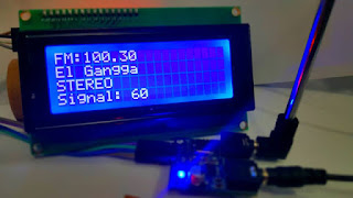
Berikut adalah Contoh Project Digital Radio FM menggunakan Module TEA5767 dengan tombol Up dan Down untuk mencari Sinyal Radio secara Otomatis dan menampilkan beberapa info pada layar LCD.

Berikut Wiring Projectnya :

1 | #include |
Berikut data pendukung untuk Library nya :
Library TEA5767 FM Module :
https://drive.google.com/open?id=0B7t_g4hdtuILX1loNWVUblo5dFE
Library Button Module (Low Active/Internal Pullup type):
https://drive.google.com/open?id=0B7t_g4hdtuILdlR1dk53aUlhcm8
Library i2C LCD :
https://drive.google.com/open?id=0B7t_g4hdtuILeEc3Uk9ZUkVKYmM
Button Menggunakan Jenis Push Button / Tactile Switch dengan Low Aktif
(aktif jika dihubungkan ke GND) dan menggunakan internal PULLUP di arduino sehingga tidak butuh resistor pullup ke VCC.
Demikian Tutorial Singkat ini dibuat oleh Dani Ardianto
Semoga bisa bermanfaat untuk semuanya..
Info lebih lanjut bisa Hubungi saya melalui FB : https://www.facebook.com/dani.ardianto.98
info Produk FM Module TEA5767 : https://www.tokopedia.com/rajacell/tea5767-fm-stereo-module-for-arduino-76-108mhz-with-i2c-connection
Silahkan Tinggalkan pesan dan Kesan pada kolom Comment Blog ini...
reff : http://www.belajarduino.com/2016/05/membuat-radio-fm-stereo-reciever-dengan.html
Membuat jam digital dengan seven segmen besar 9 V
Setelah Posting saya tentang jam digital disini, ternyata jika kita membuat jam digital dengan seven segmen kecil ukuran 0,56 " tidak jadi masalah karena seven segmen tersebut bekerja pada tegangan 3 Volt, tapi jika kita menggunakan seven segmen besar, yang tegangan kerjanya sekitar 9-10 volt, rangkaian tidak mampu untuk menyalakan 7 segmen tersebut.


berikut skema modifikasinya, dengan menambahkan transistor 9013 dan 9012 atau transistor sembarang yang penting NPN dan PNP dirangkai seperti gambar dibawah ini.
untuk rangkaian mesin jam dapat diunduh disini

Proses Pembuatan Jam digital dengan seven segmen gedhe

tinggi sekitar 7 Cm, tegangan kerja 9 - 10 Volt

Pemasangan transistor driver


rangkaian mesin Jam nya

uji coba untuk menyalakan 2 digit 7 segmen


susunan kabel dicatat biar tidak lupa


Hasil Akhirnya


reff : http://www.rokhmad.com/2016/03/membuat-jam-digital-dengan-seven-segmen.html


